- Description
- Specifications
- Documents
- Multimode, singlemode, and Quad options
- Built-in OTDR
- User-friendly Link Wizard
- PASS / FAIL in the field
- Simultaneous dual-wavelength measurements
- Prints official certification reports via OWLView certification software
- NIST Traceable
Reflections caused by connector interfaces “blind” OTDRs for a short period of time. The period of time it takes for an OTDR to recover from this “blindness” is commonly referred to as a “dead-zone”. During this dead-zone period, OTDRs are unable to distinguish one anomaly (e.g. breaks, shatters, bends, or even another connector) from another.
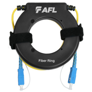
An OTDR fiber ring, which is simply an extremely long patch cable, is placed at the near-end patch panel to allow the OTDRs detector port to recover from the OTDR port dead zone. Fiber rings also enable the OTDR to measure the relative loss through the near-end and far-end patch panels (see diagram below).
Without a sufficiently long launch cable like fiber rings, the reflection from the near-end patch panel will be undetectable because it is within the dead-zone caused by the OTDR port. Likewise, at the far-end, lack of a dead-zone box will prevent the OTDR from measuring the relative loss through the far-end patch panel.
